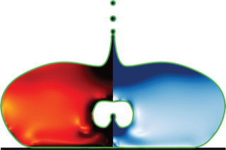
This assignment explores fundamental fluid dynamics problems using Basilisk, progressing from simple Poiseuille flow to complex Rayleigh-Bénard convection. We study both Newtonian and non-Newtonian (Bingham) fluids, examine lid-driven cavity flow with flow visualization, and conclude with thermal convection simulation. The hands-on exercises with incrementally complex implementations help develop practical CFD skills while exploring rich physical phenomena, all through Basilisk’s efficient simulation framework.
Introduction
In this working class, we’ll explore advanced fluid dynamics simulations using the Basilisk framework. Building on our previous work with heat conduction (1st-workingAssignment), we’ll now tackle more complex fluid flow problems that incorporate viscosity, non-Newtonian behavior, and thermal effects.
Learning Objectives
Implement and analyze Poiseuille flow simulations for Newtonian and non-Newtonian fluids
Understand the lid-driven cavity benchmark problem and its implementation
Extend simulations with flow visualization techniques
Explore thermal convection through the Rayleigh-Bénard configuration
Develop skills in modifying Basilisk code for different physical scenarios
Throughout this tutorial, we’ll follow a logical progression from simple to complex simulations:
Let’s begin with a fundamental fluid mechanics problem: Poiseuille flow with a Newtonian fluid.
Problem Statement
Solve for the steady-state velocity profile in a planar Poiseuille flow with a constant pressure gradient and constant viscosity . For a Newtonian fluid, the analytical solution is a parabolic profile: , where is the channel height.
The code uses Basilisk’s Navier-Stokes solver to find the steady-state solution:
#include "navier-stokes/centered.h"// Global parameterschar file_name[80];double mu_0 = 1.0; // Constant viscosity (Newtonian)int max_iter = 1e4; // Maximum iterations#define DT_MAX (1e-3) // Maximum timestep// Initialization eventevent init(t = 0) { // Set constant Newtonian viscosity const scalar mu_const[] = mu_0; mu = mu_const; // Pressure gradient (-dp/dx = 1) const face vector mdpdx[] = {1.0, 0.0}; a = mdpdx; // Initialize velocity field at rest foreach() { u.x[] = 0; u.y[] = 0; un[] = 0; }}
Key Implementation Details
The domain is a unit square with periodic left/right boundaries
No-slip boundary at the bottom ()
Slip boundary at the top (zero-gradient)
Constant horizontal pressure gradient of 1.0
Viscosity is set to a constant value (Newtonian fluid)
Convergence is monitored by tracking changes in the velocity field
At steady state, the simulation produces a parabolic velocity profile that can be compared with the analytical solution:
event end(t = end) { FILE *fp = fopen("profile.dat", "w"); // Sample the velocity profile along the x-midpoint foreach_col(0) { // Calculate exact solution: u(y) = (1/2μ) * y * (h-y) double y = y; double u_exact = (1.0/(2.0*mu_0)) * y * (L0-y); double error = fabs((u.x[] - u_exact)/u_exact); fprintf(fp, "%g %g %g %g\n", y, u.x[], u_exact, error); }}
Next, we’ll extend our simulation to handle generalized Newtonian fluids, including Bingham plastics and power-law fluids.
Problem Statement
Solve for the steady-state velocity profile in a planar Poiseuille flow with a constant pressure gradient for a generalized Newtonian fluid that follows the Herschel-Bulkley model: , where:
is the yield stress
is the consistency index
is the power-law exponent
is the strain rate
The generalized Newtonian model can represent:
Newtonian fluid: ,
Power-law fluid: ,
Bingham plastic: ,
Herschel-Bulkley: ,
The most important addition in this code is the calculation of the viscosity at each face based on the strain rate tensor:
Mathematical Background For generalized Newtonian fluids, the stress tensor is related to the deformation tensor by:
where the equivalent viscosity for a Herschel-Bulkley fluid is:
To prevent numerical instability when , we use regularization:
Compute viscosity as normal where strain rate is non-zero
Cap the viscosity at where needed
Handle special cases for different values of and
This code allows us to study how different fluid models affect the velocity profile, from the parabolic profile of Newtonian fluids to the plug flow region characteristic of Bingham plastics.
The lid-driven cavity is a classic benchmark problem in computational fluid dynamics.
Problem Statement
Solve for the steady-state flow in a square cavity with a moving top lid. The fluid is Newtonian with a constant viscosity, and all walls have no-slip boundary conditions except for the top wall, which moves at a constant velocity .
Lid-Driven Cavity Characteristics The lid-driven cavity flow exhibits several key features:
Primary vortex in the center of the cavity
Secondary corner vortices at low Reynolds numbers
Benchmark for testing numerical schemes
Reynolds number defined as Re = ρUL/μ = 1/μ (with ρ=1, U=1, L=1)
At low Reynolds numbers (high viscosity), the flow reaches a steady state with well-defined vortex structures. As Re increases, the flow becomes increasingly complex.
2.2 Lid-Driven Cavity with Flow Visualization (2-LidDrivenCavity-Newtonian-dieInjection.c)
To better visualize the flow patterns, we can add a passive tracer (dye) to the simulation:
#include "navier-stokes/centered.h"#include "die-injection.h"// Die injection parametersevent init (t = 0) { // Set constant viscosity for Newtonian fluid mu = muv; // Initialize velocity field foreach() { u.x[] = 0; u.y[] = 0; un[] = 0; }}int main() { // Initialize grid and parameters init_grid(1<<LEVEL); L0 = 1.0; origin(-0.5, -0.5); DT = MAXDT; TOLERANCE = 1e-5; CFL = 0.25; // Die injection parameters tInjection = 0.05; // Inject the die after flow is established xInjection = 0.00; // X position (center of cavity) yInjection = 0.40; // Y position (center of cavity) // Run simulation run();}
The die-injection.h header defines a scalar field that is transported with the flow:
// Define the scalar field for the diescalar T[];scalar * tracers = {T};// Initialize the die tracer to zero everywhereevent init (t = 0) { foreach() T[] = 0.0;}// Inject the die at the specified timeevent inject_die (t = tInjection) { foreach() { double dist = sqrt(sq(x - xInjection) + sq(y - yInjection)); if (dist <= dieRadius) T[] = 1.0; }}
This tracer provides a clear visualization of the flow structures and their evolution over time, revealing the complex patterns that develop in the lid-driven cavity.
Part 3: Exercise Development
3.1 Modifying 2-LidDrivenCavity-Bingham.c for exercise
For the first exercise, I recommend modifying the lid-driven cavity simulation for Bingham fluids. Here are some suggestions for redacting parts of the code:
Exercise: Implement Bingham Plastic Model in Lid-Driven Cavity
In this exercise, you’ll modify the lid-driven cavity code to simulate a Bingham plastic fluid. Complete the missing parts of the code to:
Calculate the deformation tensor components at face centers
Compute the second invariant of the deformation tensor
Implement the regularized Bingham viscosity model
Apply the viscosity at cell faces
You should run simulations with different yield stress values to observe how the flow structure changes.
event properties(i++) { foreach_face() { // TODO: Calculate deformation tensor components double D11 = /* Your code here */; double D22 = /* Your code here */; double D12 = /* Your code here */; // TODO: Calculate second invariant (D2) double D2 = /* Your code here */; double mu_local; if (D2 > 0.) { // TODO: Implement regularized Bingham model double temp = /* Your code here */; mu_local = /* Your code here */; } else { // Handle zero strain rate case mu_local = (tauy > 0.0) ? mumax : MU_0; } // Apply viscosity muv.x[] = fm.x[] * (mu_local); }}
Observe and explain the formation of unyielded regions (plug flow)
Compare streamline patterns for different yield stress values
Investigate convergence behavior as yield stress increases
Plot velocity profiles across horizontal or vertical sections
Solution Hints:
Deformation tensor components must be calculated from velocity gradients
Second invariant:
Bingham model: , with regularization to prevent division by zero
Remember to use the appropriate spatial averaging for face-centered calculations
3.2 Modifying 2-Rayleigh-Benard.c for Exercise
Exercise: Implement Rayleigh-Bénard Convection
In this exercise, you’ll implement a simulation of Rayleigh-Bénard convection using the Boussinesq approximation. Complete the missing parts of the code to:
Set up the domain and boundary conditions
Initialize the temperature field with a small perturbation
Implement the buoyancy force in the acceleration event
Set up temperature diffusion
Calculate and monitor the Nusselt number
You’ll explore how the Rayleigh number affects convection patterns.